- Electronic Components
The fundamentals of heat dissipation systems in electronics
Contents
How heat dissipation works in electronics
Circuits used in electronics, which heat up with use, become unstable if their temperatures rise above 100°C to about 120°C. Therefore, it is important to implement appropriate heat dissipation systems. This article explains the optimal heat dissipation systems used in electronics.
The figure below shows an example of a heat dissipation system for an integrated circuit (IC) mounted on the printed circuit board (PCB). On top of the IC, multiple components are stacked such as, a polymer material called a thermal interface material (TIM), a copper plate called a heat spreader, another TIM, and a heat sink. The heat generated by the IC will flow towards the heat sink and the PCB. Although other heat transfer routes exist, they can be ignored due to the small amount.

Determining the amount of heat flowing toward the heat sink
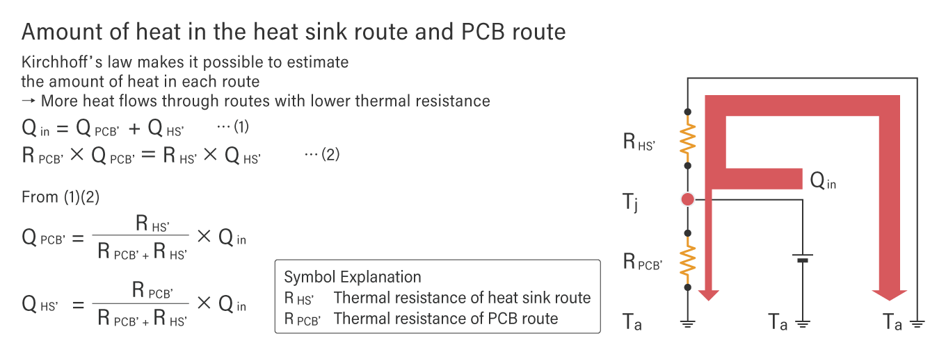
The amount of heat flowing towards the heat sink and the PCB can be estimated using Kirchhoff’s law, which is used to find the sum of currents. The amount of heat flowing through each side is proportional to the reciprocal of the thermal resistance value and is expressed by the equation below. From this equation, it can be seen that more heat flows to the side with lower thermal resistance. In other words, by making the thermal resistance on the side with the heat sink as low as possible, more heat will flow to the heat sink than to the PCB.
Determining the target thermal resistance values
If the IC generates 70W of heat, and 80% of that heat goes to the side with the heat sink, then 56W of heat flows through the heat sink. If the allowable temperature of the IC is 100°C and the maximum ambient temperature after heat dissipation is 45°C, the target thermal resistance on the side with the heat sink is 0.98 [K/W].

This thermal resistance is the sum of the thermal resistance of the heat dissipation components on the side with the heat sink: TIM1, heat spreader, TIM2, and heat sink. In other words, to achieve the target total thermal resistance, each component will have a specific thermal resistance value. Since this concept is similar to budget allocation, this is often referred to as the “thermal budget”.
The below graph shows the thermal resistance of the four heat dissipation components, totaling 0.98 K/W. Since the heat dissipation efficiency and cost will vary depending on each component, it is important to consider the most cost-effective design.

Designing heat dissipation targets for each component
Each of the various components used to dissipate heat must be considered separately. For example, the thermal resistance of a heat sink is calculated using the following three points before determining a final value.
- Type of heat sink
- Type of fan
- The rate of air flow between the fan and the heat sink
A heat spreader, which is a copper plate, distributes heat and has different thermal resistance values at different locations, which must be calculated in advance.

Dexerials offers a variety of thermal conductive sheets such as acrylic, silicone and carbon fiber sheets that features excellent thermal conductivity and flexibility. A new carbon fiber ‘Noise Suppression Thermal Conductive Sheet’ that achieves both noise suppression and thermal dissipation was also developed. Therefore, it is important to note the type of TIM to achieve dissipating heat and reducing costs.
- SHARE
 Back to top
  Contact us


