
- 接合関連
6G時代を見据える「低誘電ボンディングシート」—— スマートフォンの内部進化の脇役
目次
ミリ波に対応するスマートフォンの内部進化
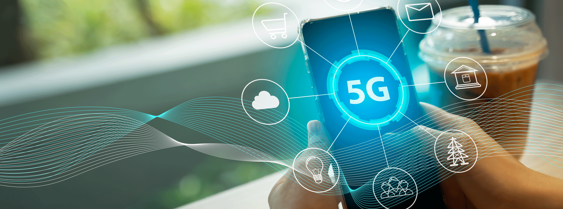
現在の5Gスマートフォンは、ミリ波帯(28GHz)の通信インフラの整備遅れや通信距離の短さの課題があり、使い勝手の良いSub6と呼ばれる6GHz以下の帯域を主に使用していますが、今後ますます通信量が増えていくことを考えると、ミリ波(28Ghz)帯域をメインとした使い方に移行していくことが確実とみられています。また2030年頃には、90GHz〜300GHzのサブテラヘルツ波や、3THzほどの非常に高い周波数帯域を使う6G通信の実用化も始まることが予想されています。
本記事では、スマートフォン内部の高周波対応アンテナの回路基板にFPCを採用する技術と、平行して重要となる伝送損失の低減技術についてご紹介します。記事の最後には、その進化に対応して開発された、デクセリアルズの低誘電ボンディングシートについて解説します。
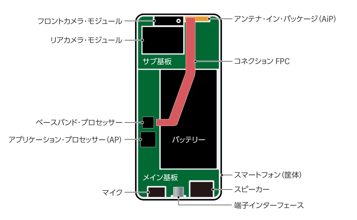
以下の図は今年(2023年)に店頭に並んでいる、最新のスマートフォンの内部構造をイラスト化したものです。低誘電の特性を持つボンディングシートが、赤く塗りつぶされた部分のコネクションFPCと呼ばれる部品に使用されています。コネクションFPCは、黄色で塗りつぶされた5Gのミリ波域の無線信号を受信するアンテナ・イン・パッケージ(AiP)という部品と、受け取った無線信号の計算処理を行うメイン基板の間をつないでいる配線基板のことを指します。コネクションFPCは受信した下り信号をメイン基板側に送るだけでなく、メイン基板側で処理した信号をAiPに渡して、アンテナから上りの信号を発信する経路にも使われています。
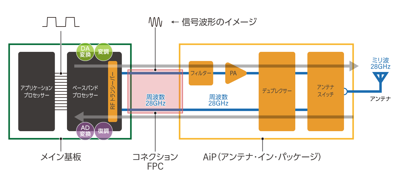
以下は、スマートフォンの通信に関わる構成要素と送受信処理の流れを示した例になります。一番左がアプリケーションプロセッサーと呼ばれるICでスマートフォンの頭脳(パソコンのCPUに相当)です。一番右側がアンテナになり電波の送受信がここで行われます。
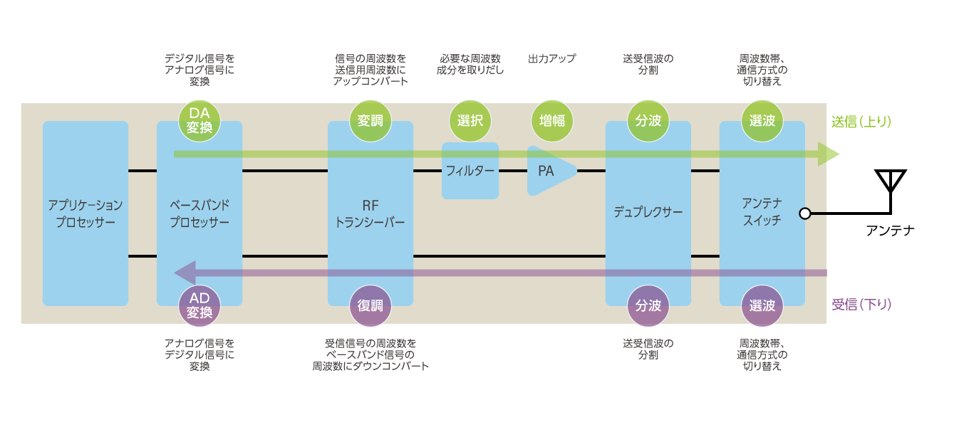
まず、構成要素について説明していきます。下図の左側にあるアプリケーションプロセッサー、ベースバンドプロセッサーは、メイン基板と呼ばれる比較的大きなプリント基板に搭載されています。前出のAiPは、信号波の変調を行うRFトランシーバーからアンテナまでの部品を一つのパッケージしたものです。通常、アンテナは電波を効率よく送受信するため、筐体外装近くにあり、メイン基板とは離れる形となります。これらを電気回路的に接続するのがコネクションFPCになります。スマートフォンの設計次第では、筐体長辺の半分以上の長さになることもあります。
ここではミリ波帯(28GHz)のAiPを例に説明をしますが、現在のところコネクションFPCには周波数8−10GHzのアナログ信号が行き来しています。AiPに搭載されたRFトランシーバーで送信(上り)時には「アップコンバート」、受信(下り)時には「ダウンコンバート」と呼ばれる周波数変換が行われます。これは28GHzの電気信号は、伝送路で減衰・損失が起こりやすいためです。
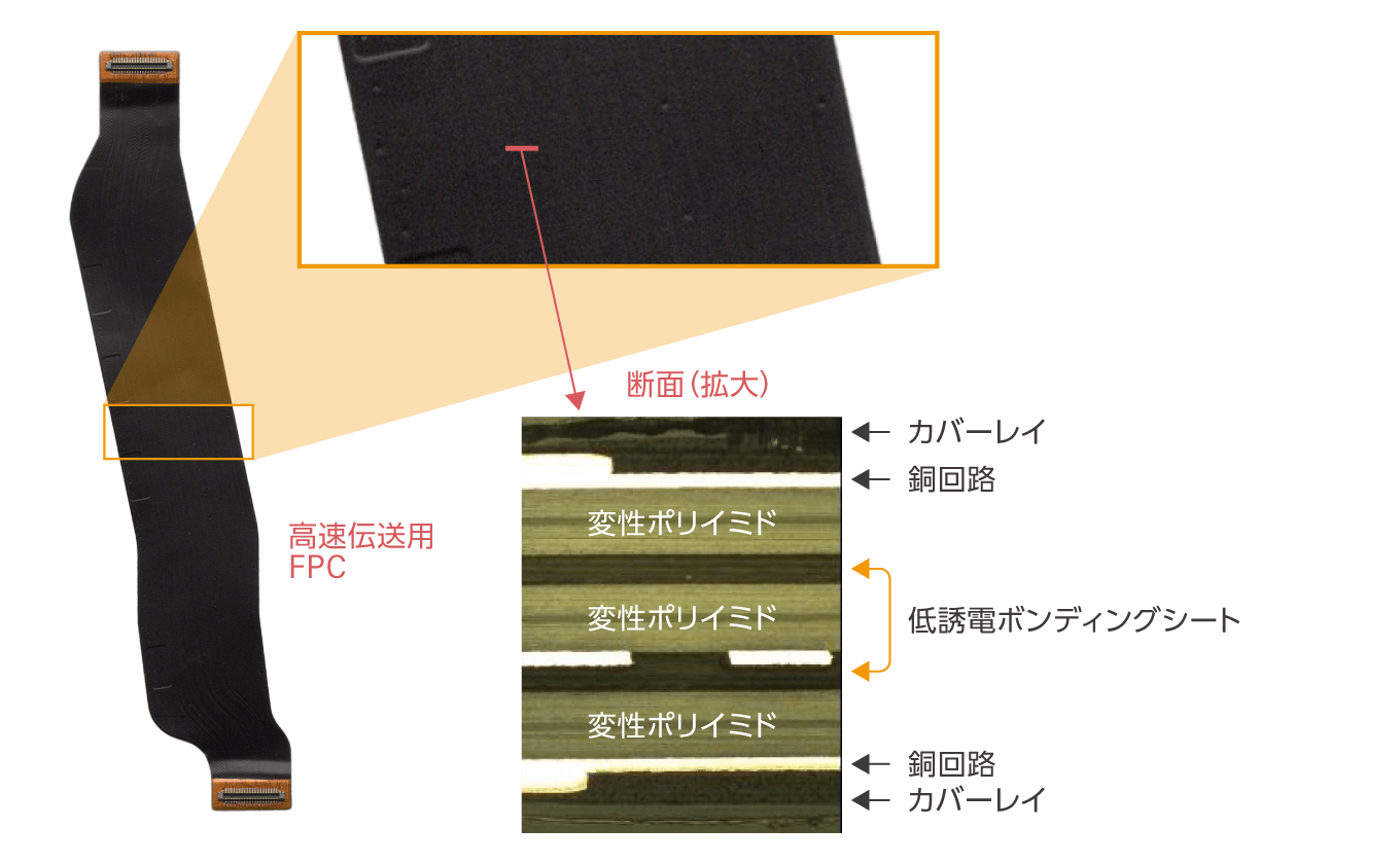
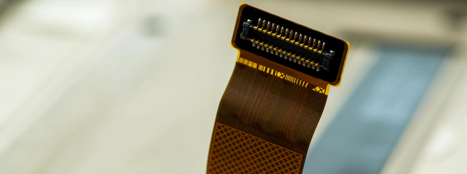
以下は当社の低誘電ボンディングシートが採用されているコネクションFPCの断面になります。変性ポリイミド(Modified PI)を積層している部分に、デクセリアルズが開発した低誘電ボンディングシートD5300シリーズが使用されています。
FPCそのものを28GHz対応のアンテナに
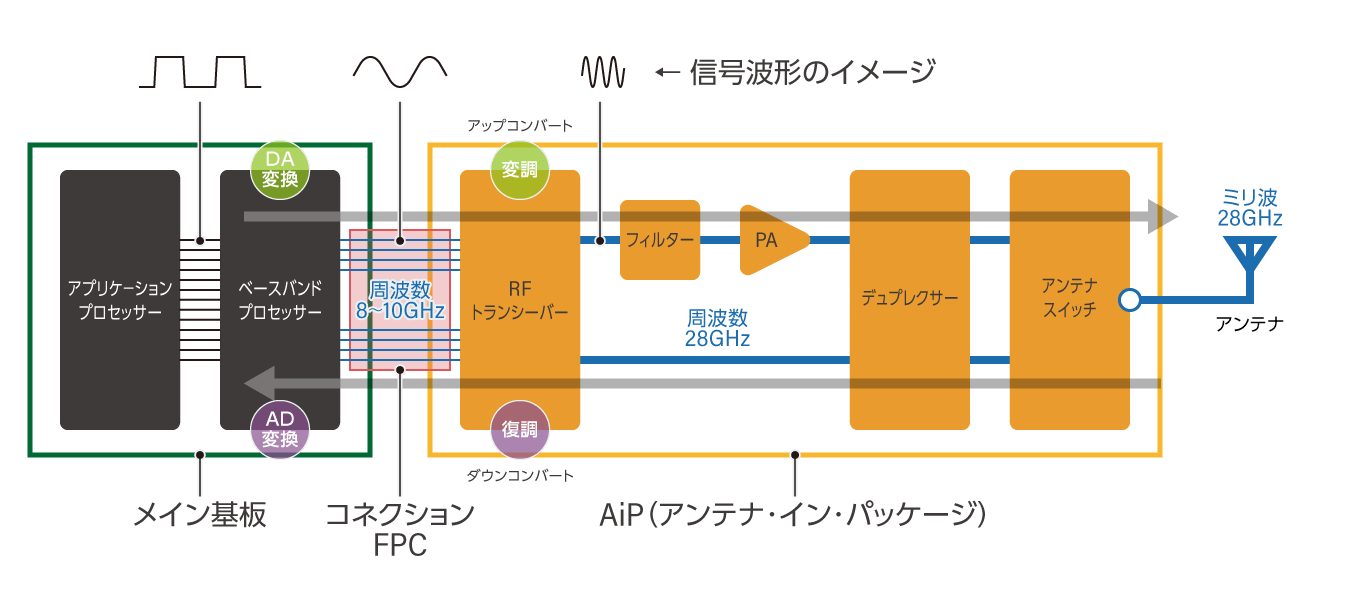
一方、以下は2023年の後半からスマートフォンでの実用化が始まっていくと目されている技術の模式図です。アンテナが受信したミリ波は、28GHzのままAiPからFPCを経由しメイン基板へと送られています。メイン基板からの上りの信号も、28GHzの高周波で発信されます。この仕組の実現には、コネクターやコネクションFPCでの高周波のアナログ信号の減衰をできるかぎり低減する必要があります。8GHzに周波数を落とさず、28GHzのままで信号をやり取りしたほうが、アンテナ側の処理がシンプルになり機能の簡素化や機能統合が可能になり処理速度は速くなります(下図参照)。そのため今、この仕組みの実現がさまざまなアプローチで研究されています。
上記の仕組みをさらに進化させ、アンテナ基板にFPCを採用する試みも検討されています。現在、スマートフォンのアンテナにはリジッド基板やセラミック基板に、アンテナ回路となる金属線をエッチングや焼付でパターン形成しています。その固いリジッド基板、セラミック基板の代わりに、薄くて折り曲げ可能なFPCそのものをアンテナにしてしまうというアイディアになります。FPCはリジッドやセラミックに比べてコストが安く、またスマートフォンの薄型化にも貢献できると考えられています。
FPCをミリ波対応のアンテナ基板とするには、28GHzの信号を流せるFPCの開発が必要です。当然、FPCを積層するボンディングシートにも、ミリ波対応の低誘電性が求められます。ボンディングシートの低誘電性については、こちらの記事に詳しく解説しましたので、ぜひご一読ください。
スマートフォンのミリ波帯域利用でさらに重要となる「熱対策」
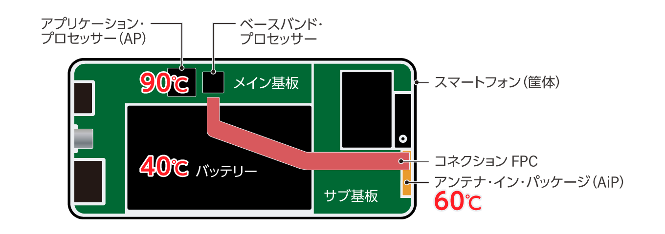
以下は現在のスマートフォンの内部構造のイラストになります。とくに熱対策が必要となる場所を黄色の字、目安の温度を赤字で示しました。
アプリケーションプロセッサー(AP)は、スマートフォンの情報処理を中心的に担うICチップで、重い処理を行うと温度が90℃前後にまで上がることがあり、周辺のデバイスもAPの発熱の影響を受けます。この他、AiPは約60℃、バッテリーは約40℃ぐらいまでの温度上昇で収まるように、多くのスマートフォンが設計されています。
先述のように、これから登場するスマートフォンではミリ波帯を使用するようになっていくことが確実とみられていますが、そうなったときに問題となるのが、スマートフォン筐体内の高温環境です。AiPや信号処理用のICなど、発熱源となる部品が増えることにより、スマートフォン内部の温度が上がりやすくなります。
スマートフォン内部の温度が上昇すると、FPCに使われている変性ポリイミドなどの樹脂の温度も高くなります。一般に樹脂は温度が上昇すると、以下の右グラフのように誘電正接が悪化することが知られており、FPCなどの回路基板において伝送信号に遅延が起きる可能性が出てきます。
こうした理由から、高周波帯域の信号を利用する回路基板では、温度が上昇しても誘電正接が変化せずに、信号ロスも増えない、絶縁材料で構成されたFPCが理想となります。
スマートフォンの未来を見据えた低誘電ボンディングシート
当社では、先に示したように周波数を落とさずにFPC上で信号をやり取りする設計変化や、FPCそのものをアンテナ化するといった変化により、FPC上を流れる信号がより高い周波数に変わっていくと考えています。また、スマートフォン内部の発熱源の増加によりFPC自体の温度上昇が起こることも考えられます。このため、高い周波数や高温環境でも低く安定した誘電特性をもつボンディングシートが必要と考えています。
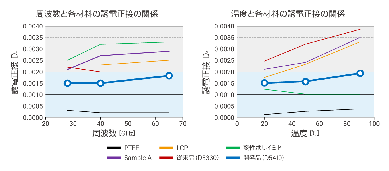
下図は、各絶縁材料の誘電特性(誘電正接)を示したものです。赤線がすでに発売をしているボンディングシート(型番:D5330)、青い線がまもなく上市を予定している開発品になります。左側のグラフは、誘電正接と周波数の関係を示したものです。デクセリアルズでは液晶ポリマー(LCP)よりも優れた誘電正接となるDf<0.002をターゲットとしていますが、従来品(D5330)がわずかにターゲット域を外れているのに対して、開発品はターゲット内に収まっていいます。右側のグラフは、誘電正接と環境温度の関係を示したものです。開発品は90℃までターゲット内に収まっており、変化量自体も抑えられています。
低誘電ボンディングシートは、高速伝送用FPCの主要素材である液晶ポリマーや変性ポリイミドを低コストで接着することが可能で、既存の生産設備を用いた5G(ミリ波)信号対応のFPC製造に貢献します(詳細はこちらの記事をご参照ください)。来る6Gの時代を見据え、スマートフォンメーカーをはじめとするお客さまのニーズに応えるデクセリアルズの製品開発に、ぜひご注目ください。
関連記事
私たちデクセリアルズはデバイスの進化に欠かせない材料や次世代のソリューションを生み出す、マテリアルメーカーです。
電子部品、接合材料、光学材料をはじめと世界中のパートナーと新しい価値を生み出していきます。
- SHARE
当社の製品や製造技術に関する資料をご用意しています。
無料でお気軽にダウンロードいただけます。
お役立ち資料のダウンロードはこちら関連製品
関連記事
接合関連の人気記事


当社の製品や製造技術に関する資料をご用意しています。
無料でお気軽にダウンロードいただけます。
お役立ち資料のダウンロードはこちら