- Bonding Products
Characteristics “Low Dielectric” and”Low Dielectric Dissipation Factor”required for insulating materials thatconstitute circuit boards for high-speedtransmission and low dielectric bondingsheets
目次
Low dielectric properties required for circuit board insulation materials
When selecting insulating materials for use in circuit boards for high-speed transmission, the most important specifications are “dielectric constant (Dk)” and “dielectric loss tangent (Df).
Simply put, the dielectric constant is a numerical value that expresses the “difficulty of electricity to pass through. Glass and plastic are much more difficult to conduct electricity than metals, so their dielectric constants are higher. More precisely, the dielectric constant is a physical property that indicates the degree to which a material is electrically polarized (dielectric polarization) when an electric field is applied.
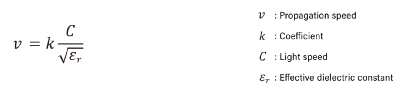
A value called “relative permittivity” is commonly used to express the dielectric constant of a material. For example, the relative permittivity of air is approximately 1, rubber is 2, water is 80, and barium titanate, a material used in capacitors, is 5000. The lower the relative permittivity value, the faster the propagation speed of the signal. The following equation shows the propagation speed of an electric signal flowing in a conductor.
Another important specification, “Dissipation Factor,” is a value that expresses the degree of loss of electric energy in a dielectric material. The larger the dielectric loss tangent for component materials used in FPCs, the more electrical energy is absorbed. The less efficiently signals can be transmitted, and the higher the frequency, the more significant this phenomenon becomes.
The following equations can express dielectric loss and transmission loss during signal propagation on a circuit board. This formula shows that the dielectric constant and dielectric loss tangent have a significant effect. This means selecting materials with low dielectric properties for high-speed signal transmission circuit boards is important.

Weaknesses of liquid crystal polymer FPCs for high-speed transmission
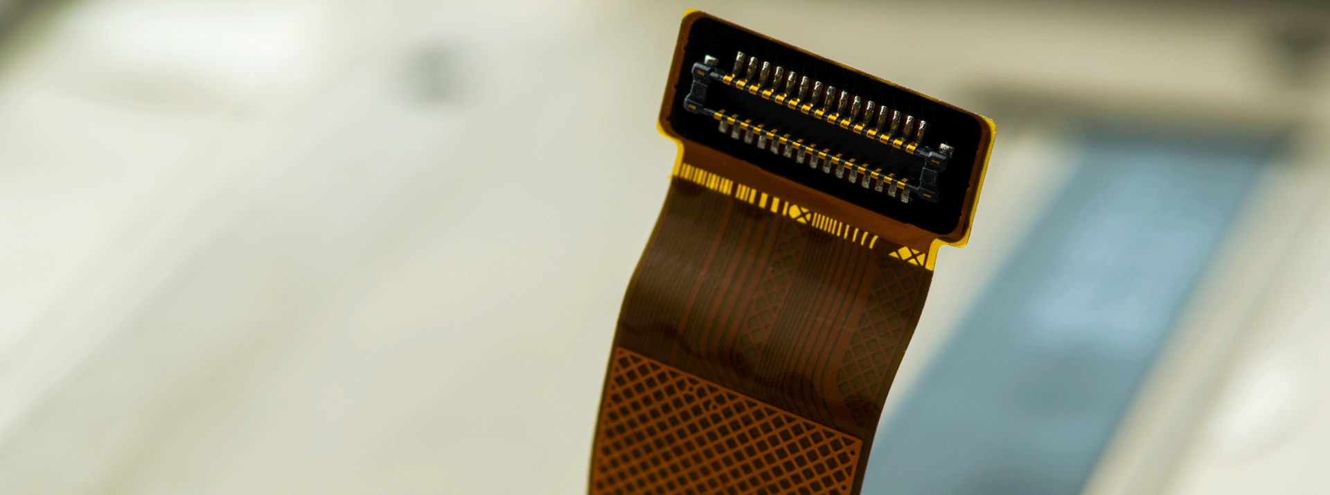
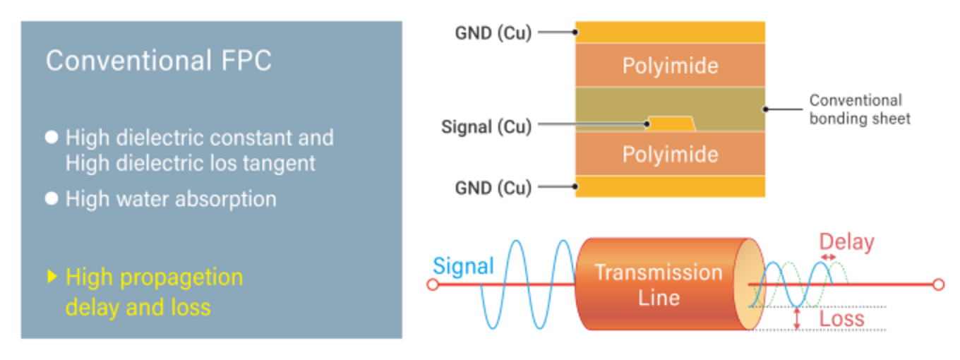
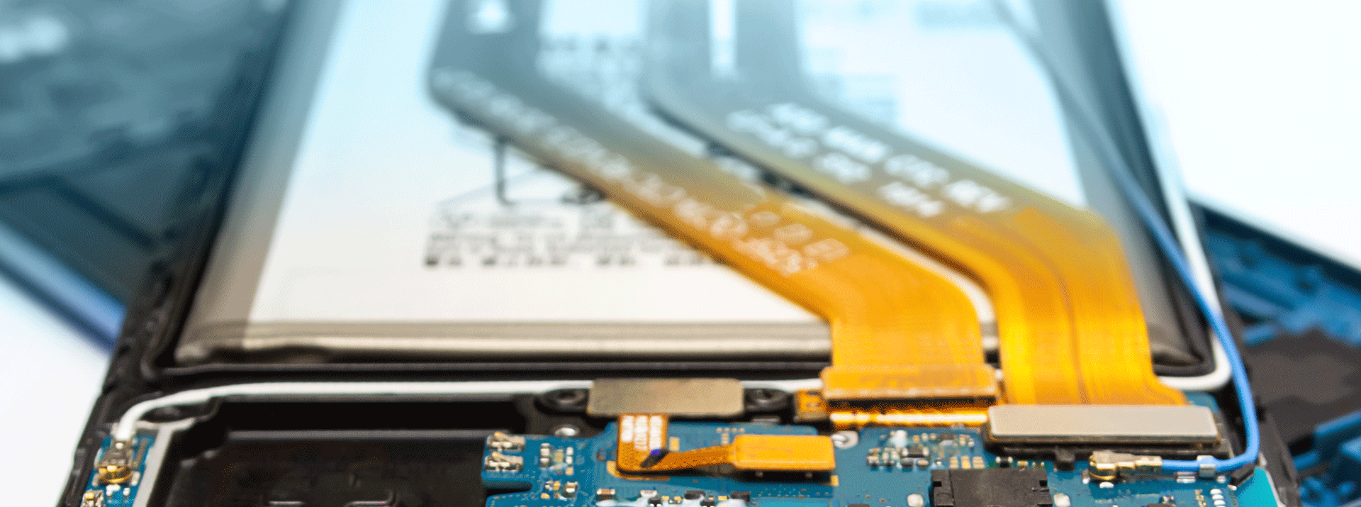
FPCs used as circuit boards must also employ corresponding materials to prevent loss and attenuation of high-speed signals. The following is a cross-sectional diagram of a multilayer FPC (three or more conductive layers) used in smartphones and other devices. A large area of copper layer is placed on the outermost layer, with the copper (Cu) circuit, through which electrical signals pass at the center, and insulating materials (polyimide resin (PI) and bonding sheets) are located inside the circuit. In practice, a double-sided CCL (copper clad laminate) with copper foil on both sides and a single-sided CCL are used as starting materials, and circuits are formed for each. These two are bonded with a bonding sheet to form the structure shown in the figure.
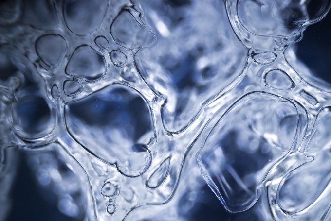
Polyimide has a high dielectric constant and dielectric loss tangent as physical properties and conventional FPCs suffer from high signal delay and loss with high-frequency components. Polyimide also has the problem of easily taking in moisture from the air (high water absorption). Since water is a substance with an extremely high dielectric constant and dissipation tangent, as the water absorption rate of the substrate increases, the degree of signal delay and loss will inevitably increase as well. Therefore, the constituent materials of FPCs for high-speed transmission must also have low water-absorption characteristics.
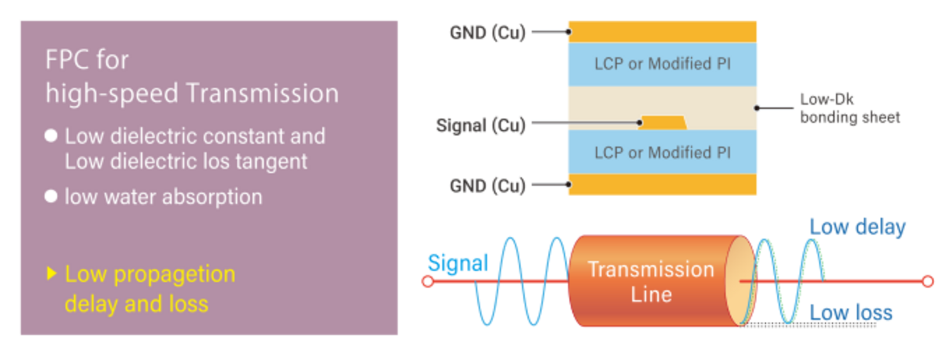
The FPC for high-speed transmission shown in the illustration below was developed to solve such problems. In FPCs for high-speed transmission, liquid crystal polymers (LCP) or modified polyimides (Modified PI) with low dielectric constant and low dielectric loss tangent properties are used instead of conventional polyimides. Materials with low dielectric constant and low dielectric loss tangent are also utilized for interlayer bonding materials (bonding sheets).
To support high-speed transmission, the base material must have a dielectric constant and dissipation factor at a level that is an order of magnitude better than that of conventional materials (polyimide). A particularly important specification is placed on the dielectric loss tangent (Df). The Df of FR-4, a material often used as a rigid board material, is 0.02, while the Df of polyimide, often used for FPCs, is around 0.01.
In contrast, LCP has a Df value of 0.002, an order of magnitude lower, and in terms of water absorption (%), another important indicator in the selection of base materials for FPC, there is a large difference between polyimide (1-2%) and LCP (around 0.04%).
However, LCP also has its weaknesses. The table below shows the characteristics of the three A, B, and C FPCs.
(A) Conventional FPC (base material = polyimide, bonding sheet = epoxy thermosetting adhesive)
(B) FPC for high-speed transmission (Base material = liquid crystal polymer, Bonding sheet = liquid crystal polymer)
(C) FPC for high-speed transmission proposed by Dexerials (base material = liquid crystal polymer or modified polyimide, bonding sheet = our low-Dk/Df bonding sheet)
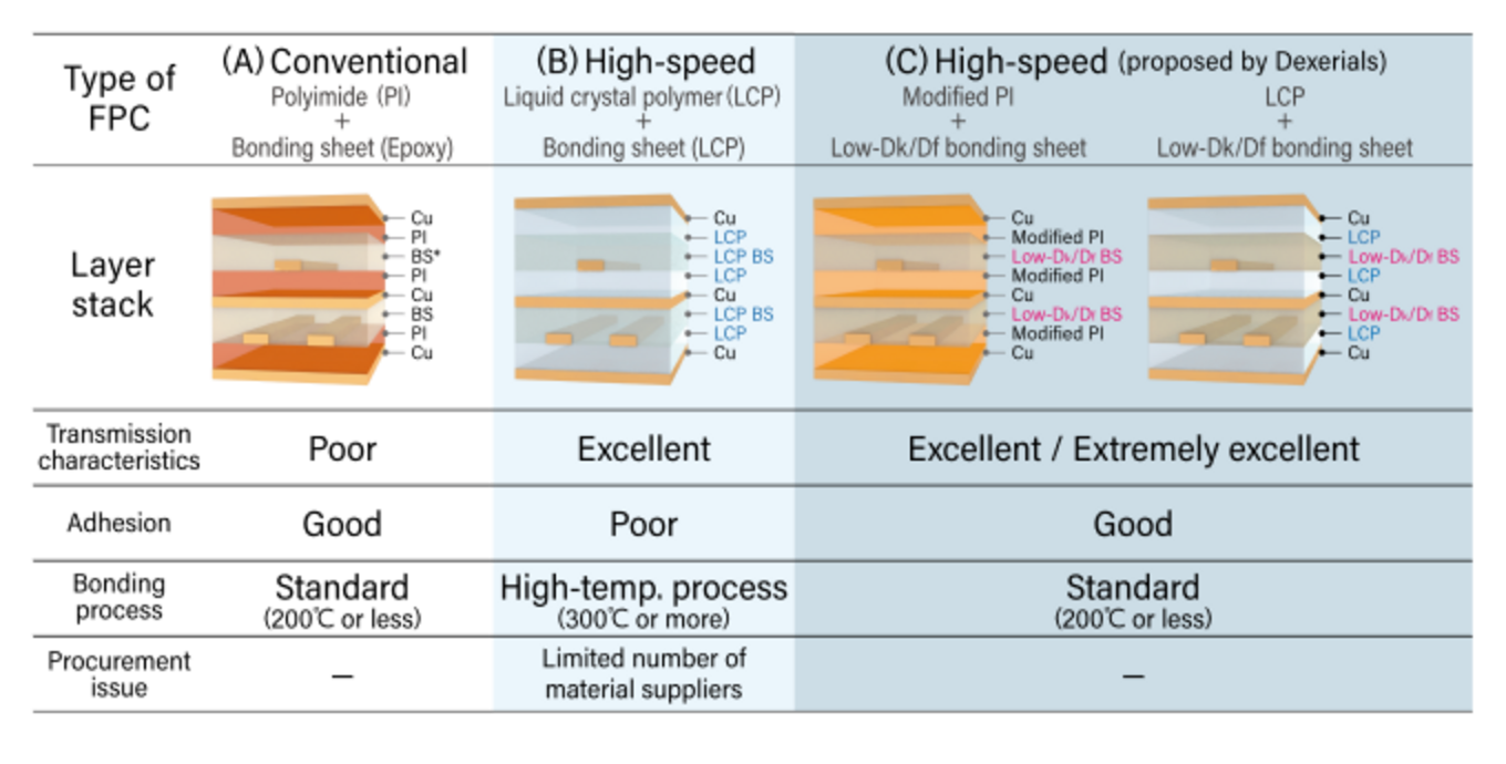
(A) is not suitable for circuit boards that require High speed transmission because the dielectric constant and dielectric tangent of the insulating material are high to begin with. (B) has excellent electrical properties because the insulating material is entirely composed of liquid crystal polymers, but it has issues such as low Adhesive to the copper that makes up the circuit (a mechanical property issue), the need for heat of over 300°C for Adhesive (an FPC manufacturing process issue), and the fact that it can only be produced by a limited number of manufacturers (a material procurement issue).
Various benefits of FPC
In contrast, (C) proposed by Dexerials offers the following advantages.
- The dielectric constant is smaller than that of LCP, and the transmission delay can be smaller than that of LCP.
- Can be bonded with a process of less than 200°C, so conventional FPC manufacturing processes/equipment can be used.
- Sufficient adhesion to LCP and modified polyimide, which are low-dielectric base materials, enables high-speed transmission while satisfying the mechanical properties required for FPCs.
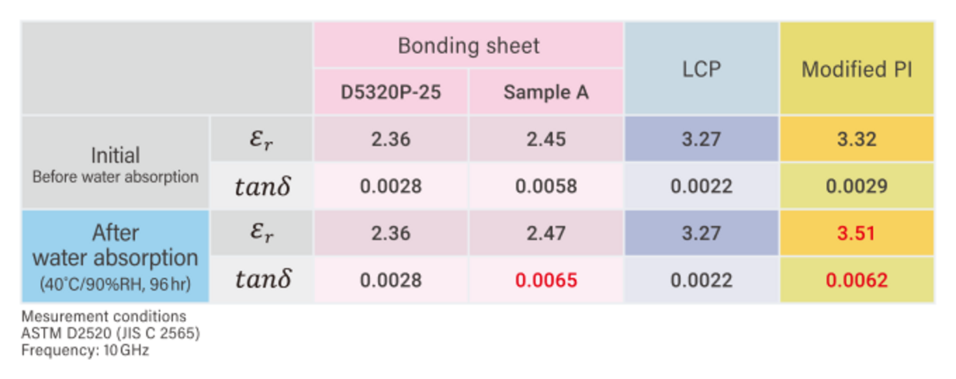
Another feature of our low-Dk bonding sheet is its low water absorbency. The table below shows the dielectric constant values and dissipation factor before and after water absorption tests conducted using each material. Our bonding sheet, like LCP, shows excellent low water absorbency with no dielectric loss tangent change in values before and after water absorption, indicating that it maintains high-speed transmission under actual usage conditions.
Strong adhesion between copper foil and substrate
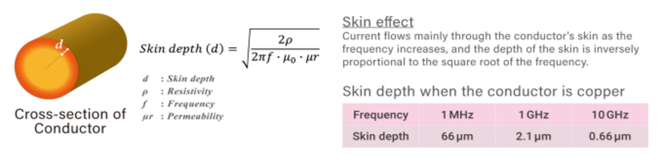
“Skin effect” is one of the important items that must be considered in the design of devices that handle electrical signals with high-frequency components, such as high-speed transmission. The skin effect is a phenomenon in which the higher the frequency of an electrical signal flowing through a conductor, the more current flows only on the conductor’s surface. The thickness from the effective surface through which the current flows is called the “skin depth,” the higher the frequency, the smaller this value becomes. As the cross-sectional area for current flow becomes smaller, the AC resistance of the circuit increases, leading to conductor loss.
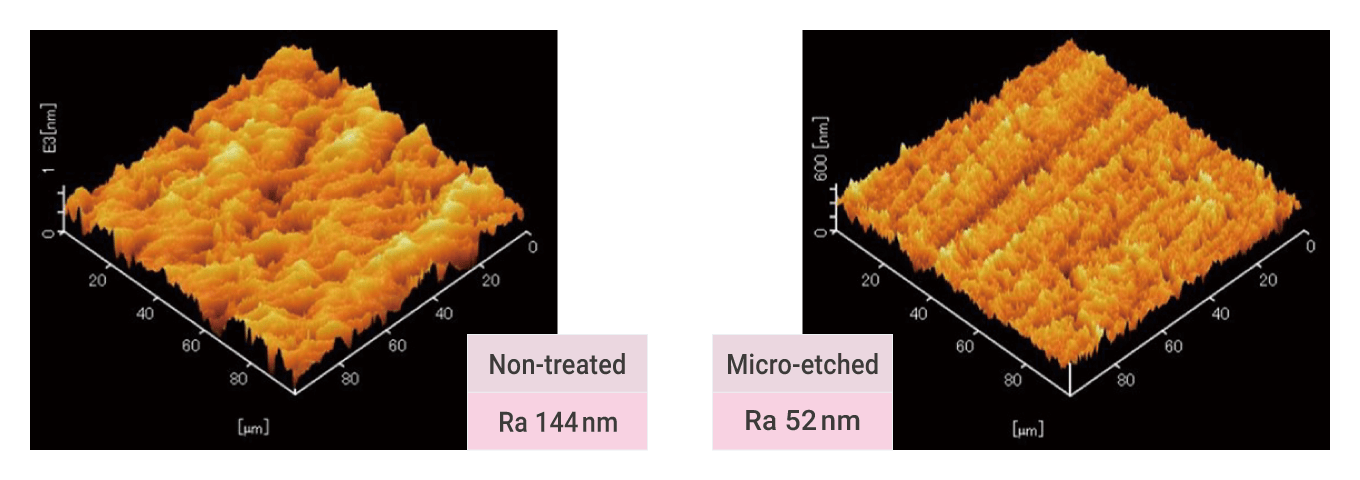
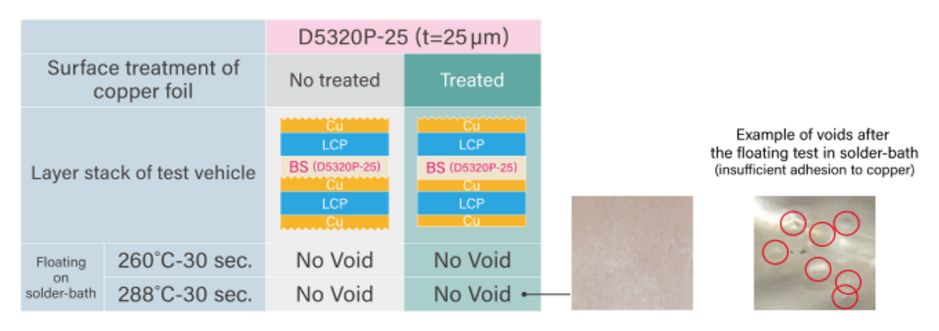
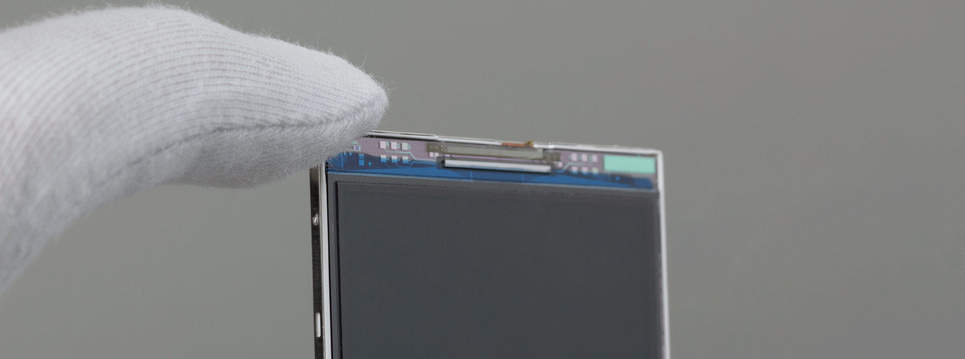
The copper surface of the copper clad laminate (CCL) used in FPC appears flat at first glance but not at the micrometer scale. As mentioned above, if the current flows only on the very shallow surface due to the skin effect, the current will flow along this rough surface, resulting in a longer conduction pathway and delayed signal arrival. Conductor loss due to skin effect is unavoidable, if high-speed transmission is assumed. On the other hand, delay can be improved by flattening the conductor surface. Therefore, in FPCs for high-speed transmission, the copper surface is smoothed by chemical treatment as shown in the picture on the right below.
It is important to note that the flatter the copper surface, the weaker the adhesion to the resin, and the more likely defects will occur that will cause the resin to peel off from the circuit. Originally, liquid crystal polymers have a property of being “hard to adhere” to other materials and are not easy materials to bond together. The bonding sheets that make up FPCs for high-speed transmission require strong adhesion between liquid crystal polymers, which are difficult to bond, and copper, which has a smooth surface.
The photo on the left below shows a sample of our low-dielectric bonding sheet (part number: D5320P-25) on a sheet with a smooth surface treated CCL laminated to it, and a solder float test was conducted. Even after floating in a high-temperature (288°C) solder bath for 30 seconds, no “voiding” occurred, as shown in the photo on the right, indicating that the initial bonding condition was maintained.
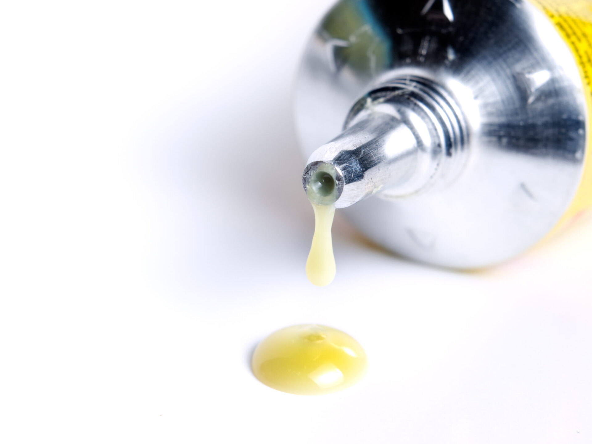
As described above, our low-dielectric bonding sheet achieves the low transmission loss required for manufacturing FPCs for 5G devices, improves adhesion between copper and LCP with a smoothed surface for high-speed transmission, and enables manufacturing using existing facilities. Another major advantage for FPC manufacturers is the product’s ability to be stored at room temperature. Ordinary thermosetting adhesives must be handled carefully, as they harden if left at room temperature and require measures to prevent condensation during use. However, our products, which can be stored at room temperature, have no problems. Detailed product specifications are listed below, so please consider our products, and contact us.
https://www.dexerials.jp/products/double-coated-tape/a1_comp_ldbs.html
Related articles

私たちデクセリアルズはデバイスの進化に欠かせない材料や次世代のソリューションを生み出す、マテリアルメーカーです。
電子部品、接合材料、光学材料をはじめと世界中のパートナーと新しい価値を生み出していきます。
- Share
We provide materials on our products and manufacturing technologies.
They can be downloaded for free.
Download Materials関連製品
Related articles
Bonding Products Popular articles


We provide materials on our products and manufacturing technologies.
They can be downloaded for free.
Download Materials