- Bonding Products
Basics of Flexible Printed Circuit (FPC) Boards and Manufacturing Technology
Contents
Basics of flexible printed circuit (FPC) boards
One of the crucial components of digital devices everyone uses every day is the flexible printed circuit (FPC) board, also known as a flexible printed wiring board. FPC boards are frequently used in the electric circuits of smartphones, tablet PCs, laptops, wearable devices, printers, digital cameras, medical devices, and automobiles. As the mobile phone market expanded rapidly with the evolution of conventional phones into smartphones, the FPC market also grew significantly. The characteristics of FPC boards enable the manufacture of smaller and thinner smartphones, tablet PCs, and other electronic devices.
This article describes the basics of these FPC boards and their manufacturing technology. Additionally, it highlights Dexerials’ materials that facilitate the manufacture of these FPC boards.
Unlike conventional rigid boards, which are solid and inflexible as their name suggests and are frequently used in electronic circuitry, flexible printed circuit (FPC) boards offer advantages, namely thinness, light weight, and flexibility, achieved by forming circuits on thin plastic films, such as polyimide.
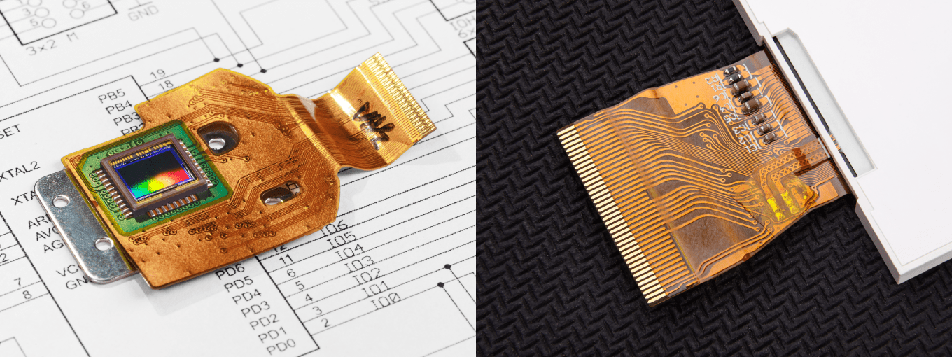
A printed circuit board may refer to either: a wiring board with conductive patterns that supply power to components and relay electrical signals between components; or a circuit board, which is a wiring board with electric functions, mounted with IC chips and other components. In addition, a collection of circuit boards that are electrically interconnected to provide a specific function is referred to as a module. Representative examples include camera and display modules. Currently, FPC boards are crucial components of these circuit boards and modules.
Contributing to reduced sizes, depths, and weights
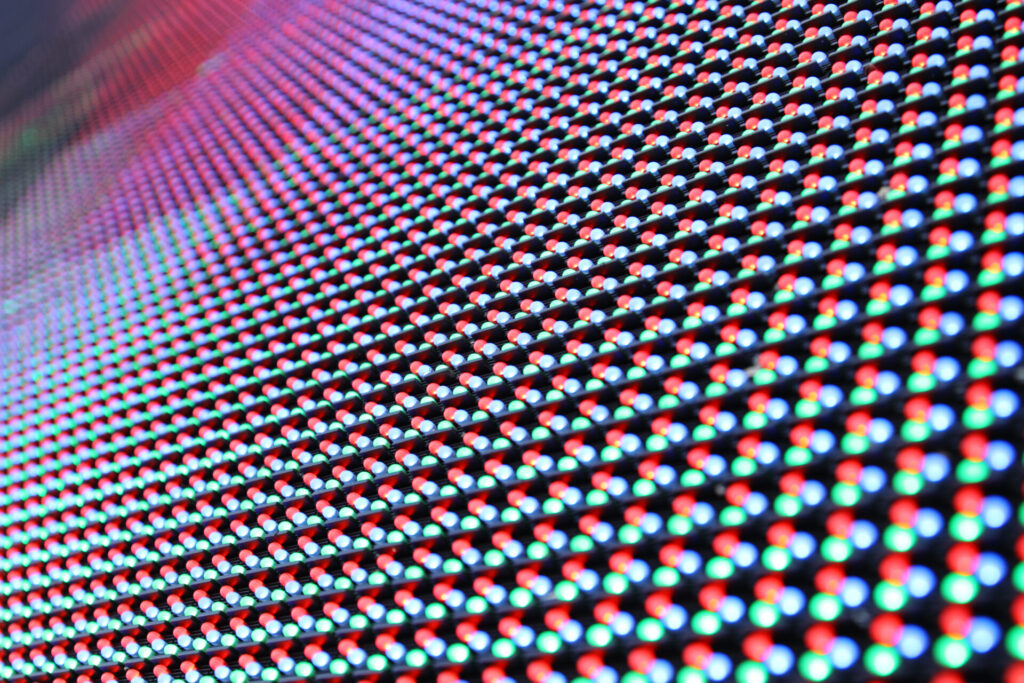
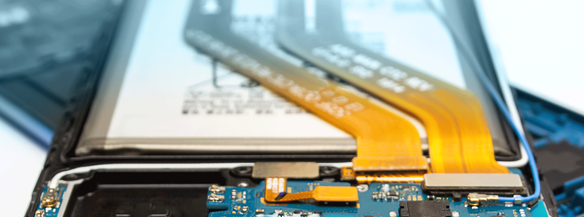
At the moment, FPC boards are adopted in many smartphone modules due to their lightweight and thin properties. They are used in, for example, display, touch-panel, camera, LiDAR, battery, and antenna modules. It is common to see a smartphone model equipped with 10 or more modules that incorporate FPC boards.
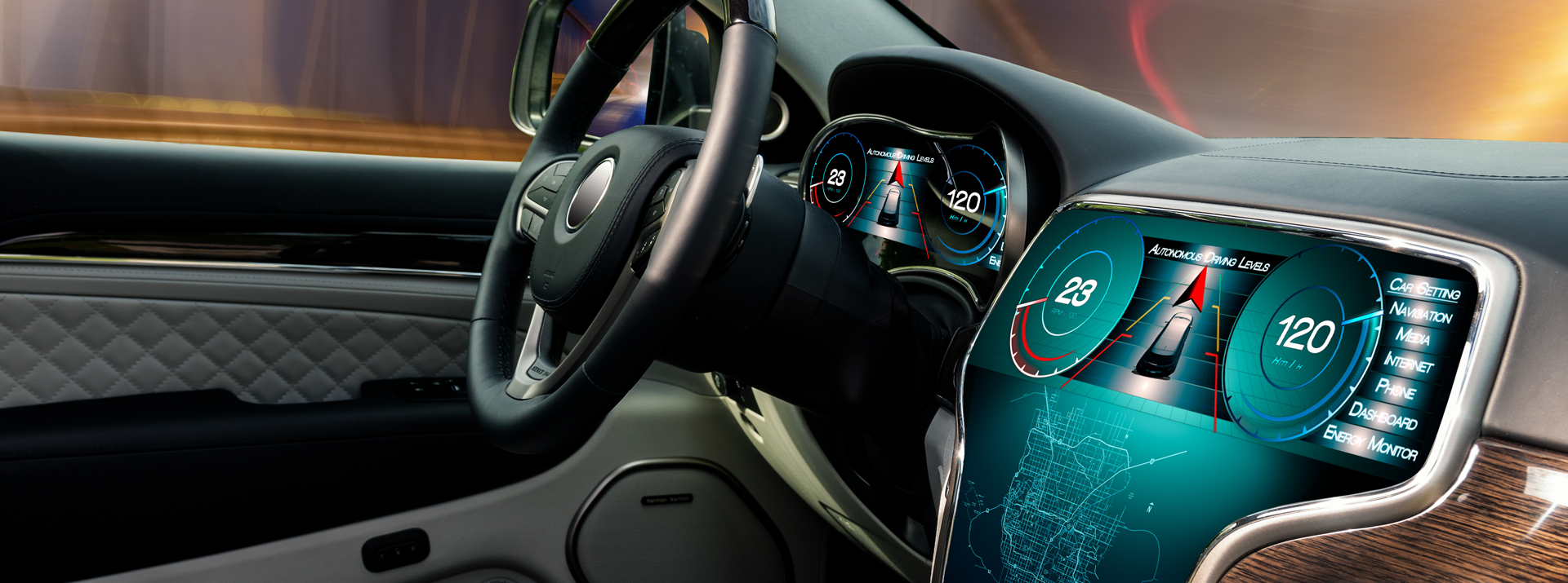
In the automotive field, FPC boards are increasingly used along with the wider adoption of electrical components. Their usage is predicted to increase even more in upcoming years. Currently, they are most commonly used in car navigation systems, headlights, switches, and air-pressure sensors for tires.
A major advantage of using FPC boards is their function as wiring boards (wiring components). They significantly simplify and streamline wiring and connection processes, expediting their inspection and repair. In addition, FPC boards are as thin as tens to hundreds of µm, and therefore make significant contributions to downsizing end products. They also assist in efficient use of housing space within end products and reduce weight per volume.
Materials of FPC boards
This section describes the difference between single-sided and double-sided flexible printed circuit (FPC) boards, their materials, and manufacturing processes. A single-sided FPC board is a standard FPC board made from a polyimide film, with copper wiring patterns on one side. It is frequently used as a wiring board due to its thin, flexible, and space-saving advantages, which contribute to reducing the overall weight of a system. It is also possible to mount components directly on FPC boards to use them as circuit boards.
A double-sided FPC board has copper wiring patterns on both sides of a polyimide film. It enables more complex circuits than single-sided FPC boards. Double-sided FPC boards also save more space as components can be mounted on both sides.
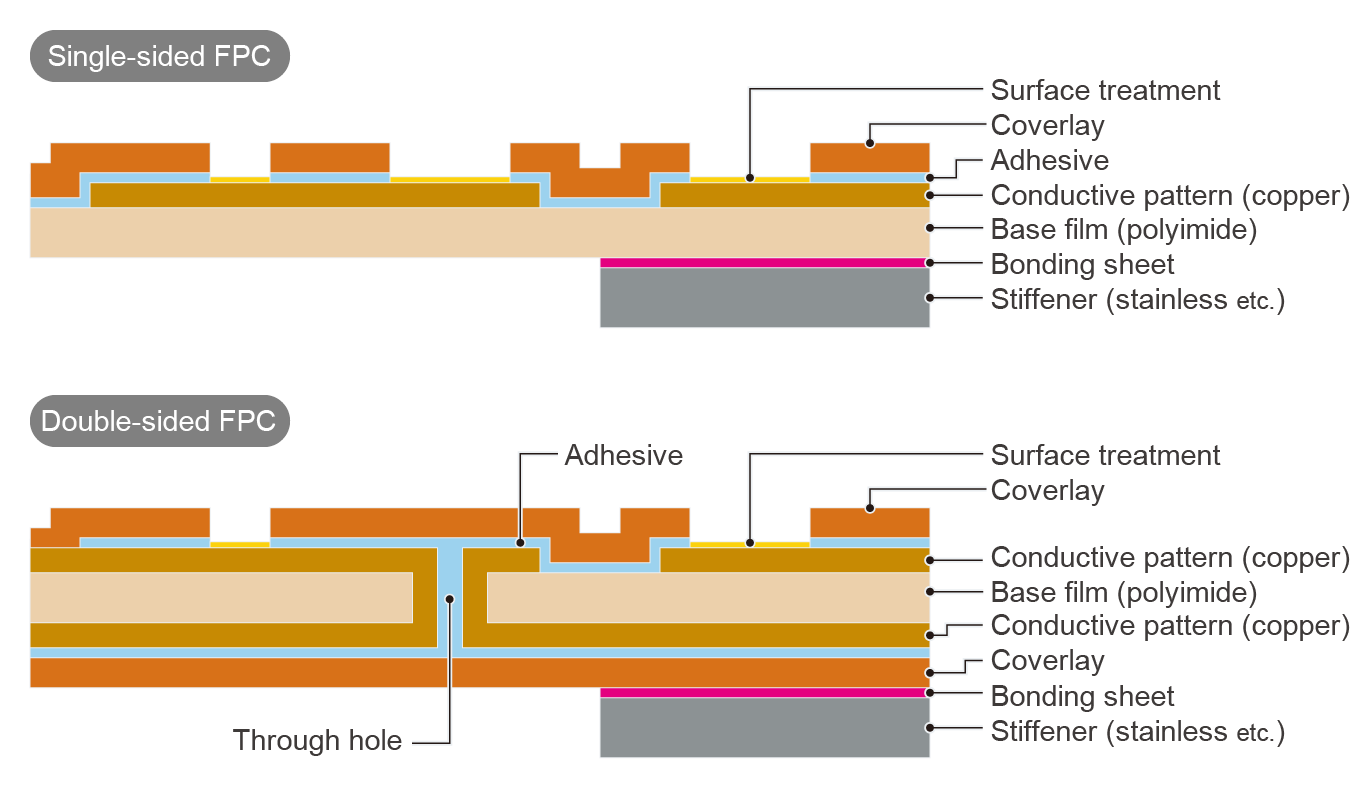
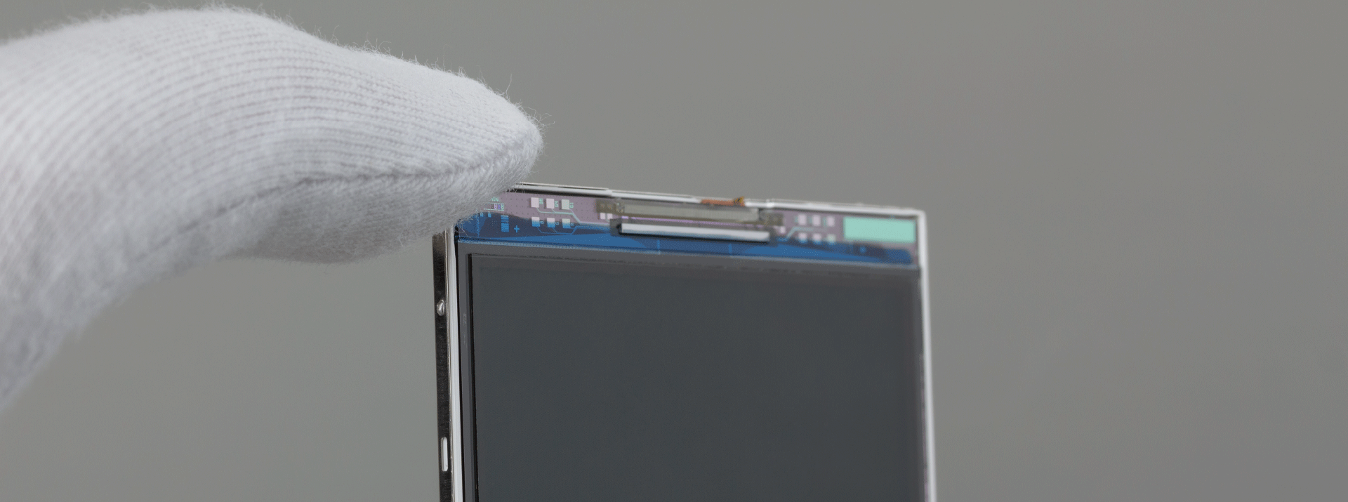
The image above shows the basic structures of the FPC boards. Conductive copper patterns are present on polyimide films, which are known as base films. These patterns are then covered by insulating layers, commonly referred to as solder resist or coverlay. The areas of the patterns where components are mounted and where connections to other circuit boards are made remain exposed. To prevent corrosion, those exposed surfaces are treated. Although FPC boards are characterized by their thin and flexible nature, they can be reinforced with flat materials, known as stiffeners, made of stainless or polyimide. Bonding sheets are used to secure these stiffeners to areas requiring additional structure or thickness for specific functions, such as component mounting.
FPC manufacturing process
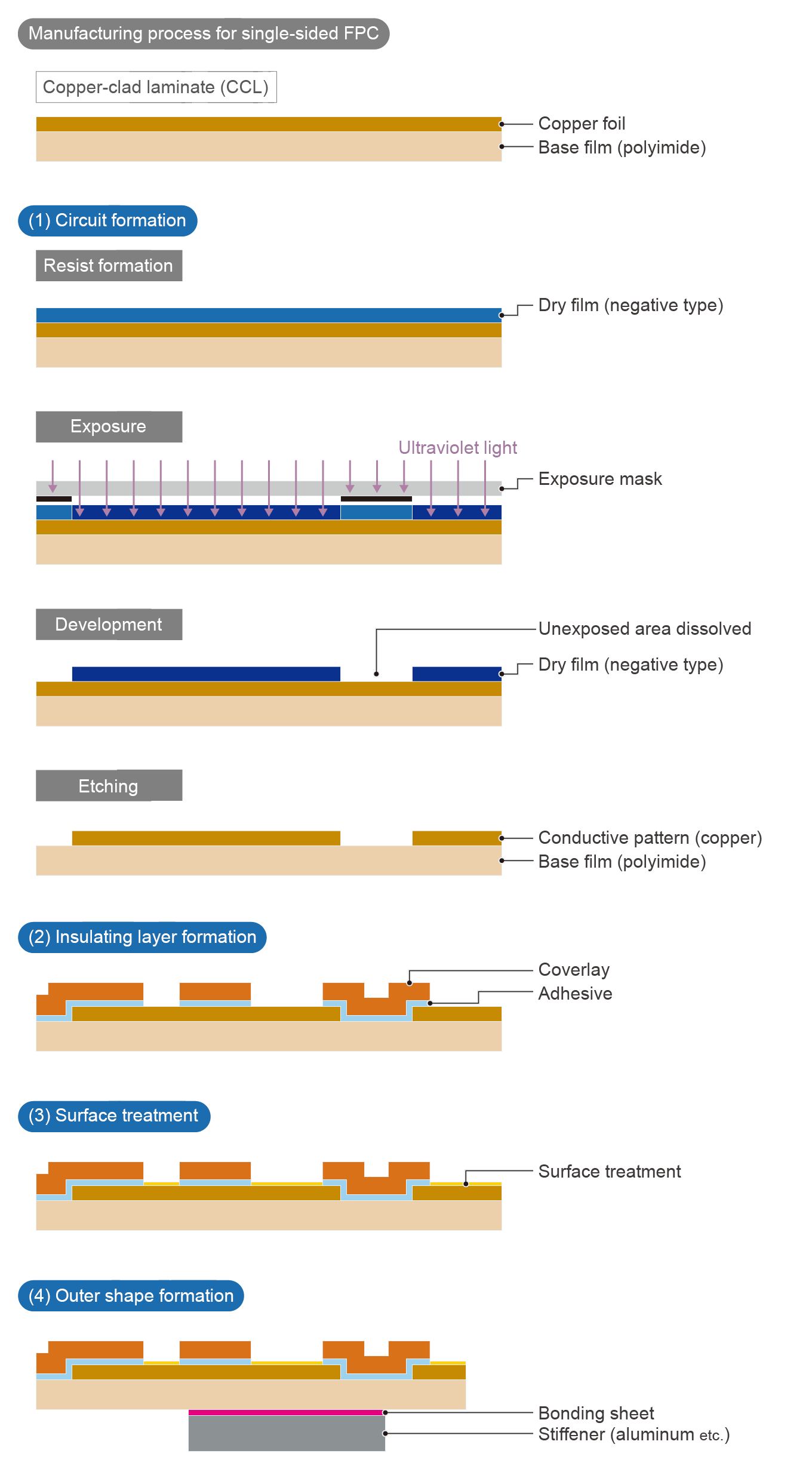
The image above shows the manufacturing process of single-sided FPC boards. The process generally proceeds in this order: (1) circuit formation, (2) insulating layer formation, (3) surface treatment (metal plating), and (4) outer shape formation.
(1) Circuit formation
Although there are various circuit formation methods, this article describes a common technique that involves photolithography.
[Resist formation]
A photosensitive resist layer is formed atop the copper foil surface of the copper-clad laminate (CCL). For rigid and FPC boards, a film resist layer (negative type), known as a dry film, is laminated.
[Exposure]
Ultraviolet light is applied through an exposure mask containing circuit patterns. In the case of negative-type resist materials, the areas in which ultraviolet light is applied undergo a change in chemical constitution that drastically reduces their solubility in a developing solution.
[Development]
The resist layer is dissolved and removed with a developing solution. At this stage, the areas of the resist that will form the final circuit patterns remain undissolved due to their extremely low solubility in the developing solution.
[Etching]
The copper-clad areas that are not covered with the resist are chemically dissolved to preserve only the areas that will form the circuits.
The resist covering the circuits is chemically removed using a solution, such as caustic soda, completing the circuit formation steps.
(2) Insulating layer formation
Pre-formed coverlays are placed at specific positions and thermally bonded for integration with the CCL. If it is necessary to mount small components, such as chip capacitors and IC chips, liquid resist, known as solder resist, may be used to form an insulating layer.
(3) Surface treatment
Untreated copper is prone to rusting (corrosion), which hinders component mounting that involves soldering. As such, copper surfaces are treated for rust resistance. In many cases, metal plating is employed for this purpose, with typical metals being gold and gold-nickel.
(4) Outer shape formation
During the outer shape formation stage, the FPC is segmented into individual boards. At this stage, stiffeners are securely bonded using thermosetting bonding sheets. After the stiffeners are bonded, the FPC is then cut into individual boards to produce the end products.
This completes the overview of the FPC manufacturing process. In practice, however, inspections are conducted during this process. Additionally, based on the shape and specifications required, extra steps may be added, and the order of the process steps can vary.
Dexerials’ bonding sheets to facilitate FPC manufacturing
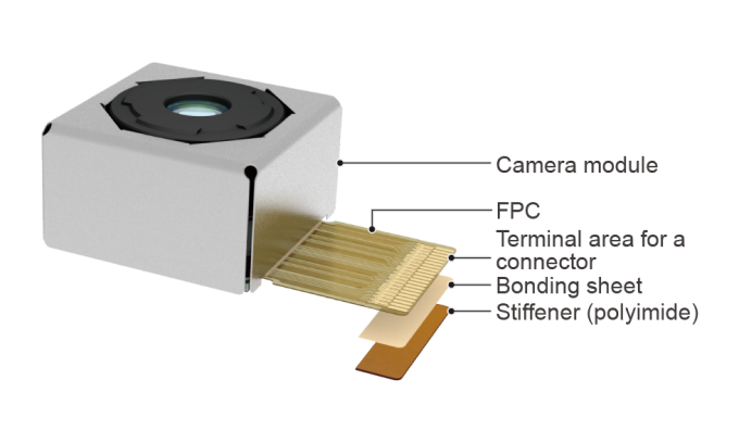
At the moment, Dexerials is developing, manufacturing, and selling bonding sheets for FPC boards. Bonding sheets, a type of thermosetting film, are used to bond stiffeners made of various materials, such as stainless (SUS), polyimide (PI), and aluminum (Al), to connector areas of FPC boards and the bottoms of camera modules. These sheets possess excellent heat-resistant and bonding properties. The key feature of our bonding sheets is their long-term preservability at room temperature. Regular thermosetting films typically require refrigeration. To use these films, they must be removed from the refrigerator and then allowed to rest at room temperature for a specified period. To store them again, they must be returned to the refrigerator. In the manufacture of circuit boards, it is common to refrigerate or freeze materials for storage in order to preserve their performance. That said, it takes much time and effort to remove and return materials beforehand according to a manufacturing schedule. Our bonding sheets’ preservability at room temperature offers a significant advantage, as it ensures constant and quick availability and also saves energy.
Modern communication devices, particularly smartphones, are expected to incorporate circuit boards designed for high-frequency transmission to satisfy the needs for high-speed and broadband communication. The materials that constitute the FPC boards used in these sophisticated smartphones must also support high-frequency transmission. To accommodate these demands, Dexerials has developed and begun mass-producing low-dielectric bonding sheets for inter-layer bonding of multi-layer FPC boards for high-speed transmission.
Anisotropic conductive film (ACF) is also an indispensable material for FPC boards, display and camera modules, and IC chips, enabling high-speed transmission. Using ACF enables thinner FPC boards when compared with conventional methods involving metal wires (wire bonding), solder balls, and mechanical connectors. It can also significantly reduce transmission loss at connection points.
Dexerials’ materials will make various contributions to FPC boards, which are used in an increasingly broader range of electronic devices. For questions about FPC boards and details on related materials, please feel free to contact us.
- SHARE
 Back to top
Bonding Products Popular articles